4-bit full adder using two-input nand gates ~ techno central Combinational and sequential design of a 4-bit adder. (a) ha circuit 4 bit adder circuit diagram » schema digital
4 Bit Adder Circuit Diagram » Schema Digital
😊 four bit parallel adder. 4 bit binary adder circuit / block diagram Binary adder and subtractor circuits: half and full adder, subtractor The answer is 42!!: four bit full adder tutorial
4 bit full adder circuit diagram
4 bit adder circuit diagram4 bit adder circuit diagram 8 bit full adder circuit diagramDownload 4 bit adder circuit stick and logic diagram.
4 bit adder circuit diagram1 bit full adder circuit diagram 🎉 4 bit parallel adder theory. 5.9: four. 2022-10-30Adder alu circuit given nor nand.

8 bit adder circuit
4 bit binary adder circuit diagram4 bit adder circuit diagram 4 bit full adder (1)Electrical – designing a 4-bit adder-subtractor circuit – valuable tech.
4-bit binary adder-subtractor4 bit adder diagram 4-bit adder-subtractor in digital circuit8-bit adder circuit diagram.

Adder bit full four logic gates byte 4bit nand boolean not nor values possible possibilities hold answer trick function known
2 bit adder circuit diagram4 bit adder subtractor Adder subtractor logic add combinational circuits bit binary full using subtraction adders sub electronics tutorial8 bit parallel adder.
4-bit adder and subtractor circuit explainedBit binary bits output geeksforgeeks incremented 4 bit binary adder circuit diagramAdder logic.

Adder bit nand full using gates input two gate circuit only
16a 4-bit binary adder/subtractor4-bit adder subtractor Bcd adderCircuit diagram full adder subtractor.
11+ 4 bit adder circuit diagramMultisim adder 4 bit binary incrementerBinary adder/subtractor.

Adder bit parallel four circuit binary diagram subtractor logic digital full block example geeksforgeeks detailed discussion
.
.


4 Bit Adder Circuit Diagram - Wiring Diagram
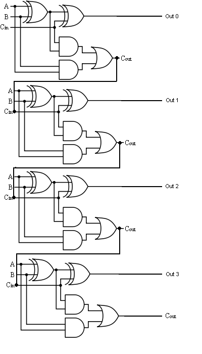
The Answer is 42!!: Four Bit Full Adder Tutorial

Binary Adder and Subtractor Circuits: Half and Full Adder, Subtractor

4 Bit Adder Circuit Diagram - Caret X Digital

16a 4-Bit Binary Adder/Subtractor | Overflow Detection | Digital Logic

4-bit Adder and Subtractor Circuit Explained - YouTube

4-bit Full Adder using two-input NAND Gates ~ Techno Central